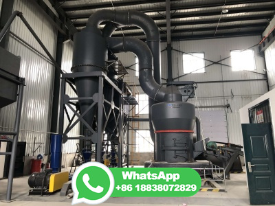
The thermal power plant is essential to maintaining the supply of electricity because it can adapt quickly to changes in demand. A thermal power plant, also known as a thermal power station, is used to transform heat energy into electric power for domestic and industrial applications. Electric power is generated by steampowered turbines, which ...
WhatsApp: +86 18203695377
Library. IGCC Process Unit Operations. A brief description of the various processing units within an integrated gasification combined cycle system is given below in reference to the block flow diagram ( Figure 2) discussed under Typical IGCC Configuration. A more detailed discussion of each of the processing unit sections is available ...
WhatsApp: +86 18203695377
Library. Typical IGCC Configuration. Figure 1 depicts the overall process configuration of a notable IGCC power generation unit located in the United States, the TECO Polk Power Plant Unit 1. This unit is quite representative of IGCC plants in general; further information is provided on the dedicated page for the Tampa Electric IGCC project .
WhatsApp: +86 18203695377
Working Principle of a Thermal Plant. The working fluid is water and steam. This is called feed water and steam cycle. The ideal Thermodynamic Cycle to which the operation of a Thermal Power Station closely resembles is the RANKINE CYCLE.. In a steam boiler, the water is heated up by burning the fuel in the air in the furnace, and the function of the boiler is to give dry superheated steam at ...
WhatsApp: +86 18203695377
Energyefficient Technologies in Direct Reduction of Iron Process 17 Waste Heat Recovery for Power Generation 18 Iron Ore Preheating Rotary Kiln Using Waste Heat Recovery System 20 Coal Gasification for Partial Substitution in Rotary Kiln 22 Waste Heat Recoverybased Absorption Chiller 23
WhatsApp: +86 18203695377
sufficient coal reserves available to keep the power station in operation should the mine experience production problems. Inside the power station, the coal is pulverised to a fine powder in giant grinding mills. This is because pulverised coal burns quickly, like gas. The pulverised coal is transported to the boiler furnace with air where it ...
WhatsApp: +86 18203695377
A process flow diagram of the proposed power plant layout is shown in Fig. 10. Based on mass and energy balances discussed in the "Layout of natural gasfired pressurized CLC" and "Layout of syngas fired pressurized CLC" sections, this has been developed for a 761 MW th plant when fired with natural gas and 800 MW th when fired with ...
WhatsApp: +86 18203695377
Below is a schematic flow diagram of an IGCC plant: Block diagram of IGCC power plant, which utilizes the HRSG The gasification process can produce syngas from a wide variety of carboncontaining feedstocks, such as highsulfur coal, heavy petroleum residues, and biomass .
WhatsApp: +86 18203695377
The application of oxyfuel combustion for coal fired power plant could be broadly classified according to: (a) oxyPC and (b) oxyCFB. On the other hand, the application of oxyfuel combustion for gas turbine based power plant could be broadly classified according to its working fluid namely: (a) CO 2 based GT cycles and (b) Water based GT cycles.
WhatsApp: +86 18203695377
Coalfired power plant process diagram. | Download Scientific Diagram Content may be subject to copyright. Coalfired power plant process diagram. Source publication +20...
WhatsApp: +86 18203695377
How a Coal Plant Works. Coalfired plants produce electricity by burning coal in a boiler to produce steam. The steam produced, under tremendous pressure, flows into a turbine, which spins a generator to create electricity. The steam is then cooled, condensed back into water and returned to the boiler to start the process over. Here's a real ...
WhatsApp: +86 18203695377
This work considers an analysis using energy and exergy of turbines for a coalbased conventional steam power plant of 500 MW under the Damodar Valley Corporation (DVC), India to optimize its ...
WhatsApp: +86 18203695377
Carbon Capture and Storage A technology which reduces carbon emissions from the combustion based power generation process and stores it in a suitable location ... Process Flow Diagram Process Flow Diagram (PFD) is a drawing which describesthe process flow for a processing plant. PFD is used to capture the main process equipment
WhatsApp: +86 18203695377![Schematic diagram of a coalfired steam power plant [11]. ResearchGate](/9howncx/254.jpg)
The fossil fuel employed in a steam turbine plant can be pulverized coal (PC), oil, or natural gas. Of these, coal is the most abundant and hence the most commonly used fuel for steam turbine ...
WhatsApp: +86 18203695377
The diagram below shows the position of an ESP within a coal fired power station flue gas system. Another important component used for flue gas cleaning is the flue gas desulphuriser (FDG), also referred to as a 'scrubber tower'; the scrubber tower is shown to the left of the ESP on the below diagram. Flue Gas System With ESP Highlighted
WhatsApp: +86 18203695377
Process flow diagram of conventional postcombustion CO 2 ... A conventional coalfired power plant with postcombustion capture has to separate carbon dioxide from a flue gas mixture in which there is a large amount of nitrogen. The oxyfuel process, by removing the nitrogen at the start, so that coal burns in oxygen instead of air, sidesteps ...
WhatsApp: +86 18203695377
a coalfired power plant or cofired plant. ... solar water heating system) based on userspecified inputs describing a system's physical configuration, its location, and the cost of installing and operating the system. SAM's ... Biomass power process flow diagram . 3
WhatsApp: +86 18203695377
As this diagram shows, the plant operates on the same principles as other fossilfueled electric generating plants—it burns coal to produce heat that turns water into steam, which then turns turbines in a generator. Sources/Usage: Public Domain. Credit: Georgia Power
WhatsApp: +86 18203695377
Nantong Power Station, a coalfired power station in Nantong, China Rooiwal Power Station in South Africa Geothermal power station in Iceland Drax Power Station, the world's largest biomass power station, in England PS10 solar power plant, concentrated solar thermal power station in Andalusia, Spain. A thermal power station is a type of power station in which heat energy is converted to ...
WhatsApp: +86 18203695377
Context 1 ... process flow diagram of the coalfired plant is shown in Figure 3. The plant has a regenerative feed water system. ... View in fulltext Context 2 ... are three exit ports...
WhatsApp: +86 18203695377
Methanol is a clean fuel and an important feedstock for the petrochemical industry. Conventionally, the coaltomethanol process generates a substantial amount of CO2 emissions with a low yield of methanol. In this study, we propose the conceptual design development of coaltomethanol process using captured CO2 from the gasification plant by implying process intensification. The base case and ...
WhatsApp: +86 18203695377
Operating a coal firedpower plant is challenging. The power plant comprises complex mechanical and electrical systems, which interact together to produce electricity. Though a coal plant full diagram involves lots of components, the simplified version in Fig. 1 is relevant to the analysis in this work. The diagram shows the main block ...
WhatsApp: +86 18203695377
Stage 1 The first conversion of energy takes place in the boiler. Coal is burnt in the boiler furnace to produce heat. Carbon in the coal and Oxygen in the air combine to produce Carbon Dioxide and heat. Stage 2 The second stage is the thermodynamic process. The heat from combustion of the coal boils water in the boiler to produce steam.
WhatsApp: +86 18203695377
Coal is the main source of electricity generation in fossil fuel based power plants. The use of coal in coalfired power plant (CFPP) causes raise in global temperature due to greenhouse gases emission responsible for global warming across the globe [1, 2]. It also has an adverse impact on the health of human being.
WhatsApp: +86 18203695377
Library. Hydrogen Production from Coal without Power Export. In cases where the goal is to produce hydrogen (H 2 ) from coal without power export, the overall flow arrangement can be further simplified. Figure 3 is a block flow diagram for producing H 2 from coal with minimal power generation. Onsite power generation is kept to a level ...
WhatsApp: +86 18203695377
Figure 1. A coal fired power plant in England. [1] Note the two tall smoke stacks where the combustion products go into the atmosphere and the shorter, wider cooling towers. Coal fired power plants also known as coal fired power stations are facilities that burn coal to make steam in order to generate electricity.
WhatsApp: +86 18203695377
1 Scope. This part of ISO 14084 specifies types of process diagrams for power plants and rules and guidelines for the preparation and representation of information in such diagrams. This part of ISO 14084 series is a collective application standard of the ISO 15519 series. This part of ISO 14084 does not apply to electrotechnical diagrams ...
WhatsApp: +86 18203695377
The thermal power plant also called a thermal power station finds use to convert heat energy to electric power for and commercial applications. In the process of electric power generation, steamoperated turbines convert heat into mechanical power and eventually into electric power. The thermal power plant, also known as a thermal ...
WhatsApp: +86 18203695377
Process flow diagram of the considered power plant. Download : Download highres image (652KB) Download : ... Exergy analysis and heat integration of a coalbased oxycombustion power plant. Energy Fuels, 27 (2013), pp. . CrossRef View in Scopus Google Scholar. Goodarzi, 2021.
WhatsApp: +86 18203695377
Oil is occasionally used to generate electricity as well. Figure n : This combustion chamber burns either natural gas or oil. Fuel flows through a natural gas line or from oil storage into the combustion chamber. Air passes through the air intake and is compressed in the compressor.
WhatsApp: +86 18203695377